X Plane 12 Plane Maker Build Your Own Aircraft Fast Tutorial.
So, you want to build your own aircraft for X Plane? It’s pretty fast and easy to get started and be flying fast. In this tutorial we will look at the important parts of what is a daunting looking program but really is quite easy!
Over the last week I have dived down the rabbit hole to build my own aircraft. I now have the SD-1 Mini Sport as well as the Cosy Mk IV canard aircraft under my belt plus a free hand design I’m exploring. Many More to come!
Why Will This Tutorial Help You!
I will unlock the essential few menu items you actually need to be successful, and this will remove the frustrations of endlessly searching for what you need. Work smarter, not harder! There are a number of items not listed in many of the long winded 20 video tutorials I have searched so I’ll give you what you need to know from the get-go! I will also create a companion video on LetsFlyVFR YouTube channel which you should find below in the near future.
Tip: I would suggest importing the pictures into Microsoft Paint and also inverting the colours.
Load pictures- Select it with the mouse – Right click mouse with cursor on the picture and select Invert Colours. This will give you a black background and white lines. It was helpful for me!
SUBJECTS.
Let’s get started with what you need.to know. Honestly if you get to the bottom of this tutorial, you’ll be more than ready and not daunted by Plane Maker in the least.
- Do Your Research to Be Successful.
- Picture References – Tips & Tricks.
- Save/Save As.
- Essential Mouse Keyboard Controls for Success.
- Aircraft V Speeds Menu.
- Engine Selection Parameters – Prop Selection.
- Bodies – Views & Controls.
- Weight & Balance – Guide.
- Wings Building Concepts.
- Add Control Surfaces Easily.
- Wing Air foil Application – It’s Easy!
- Instrument Panel 2D /3D.
- Test Flight & Adjust.
- Paint and Design.
- Completed Aircraft.
- What’s Next – 3D Program.
Do Your Research to Be Successful.

To be successful at being able to build your own aircraft in Plane Maker starts here. An excellent place for most essential is the Pilot Operating Manual (POH) in the case of General Aviation (GA) aircraft as well as manufacturers websites. The more in-depth information you can gather, the better your aircraft will be. Items such as flap limitations as well as types plus spoiler locations plus flap/slat extension angles, number of steps and what degree settings could be invaluable. So don’t leave any google search unturned to you have what you need. This is probably the hardest part of building your aircraft.
The success of your project really flies or fails at this early juncture. Getting large quality drawings of your aircraft are also super important. It’s imperative you DONOT change the scale otherwise the physical dimensions you’re aiming for will be lost. Check out below where I have some examples.
- Joystick / HOTAS – AMAZON.com
- Rudder Pedals – AMAZON.com
- Throttle Quadrant – AMAZON.com
- Gaming Chair – AMAZON.com
- VR Headset – AMAZON.com
Picture References – Tips & Tricks.
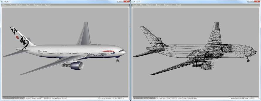
These websites will normally have the specifications including lengths of fuselage, wing sizes plus wing loadings, weights both full and empty plus a lot more! If you are able to find the actual aerofoil design which may look like N1234, it will make your aircraft 100% accurate in the X Plane world when it takes to the air.
Get a set of set of drawings of the aircraft so you can have a visual reference in the program to work with. These you can quickly import into your program and reference shapes and sizes directly off them. You can rotate and rearrange them in a paint program such as Microsoft Paint (Not 3D) as you can cut and paste while rotating them to be the correct orientation. Can I suggest the nose point to the LEFT on side views. The front view needs to point toward you and the top can point upward.
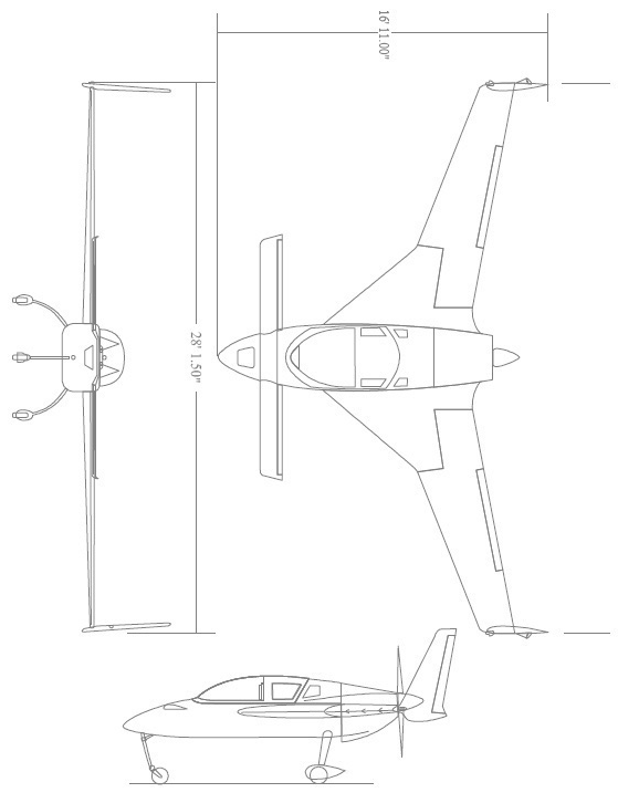
Tip: It’s worth separating the top View- Side View & Front View onto individual picture files. Do not change the zooms unless you can change them equally. Make sure they are .BMP for ease of use of use. It’s pretty easy to open the main image then select and copy each image to a NEW page without altering its dimensions. You can again make sure the orientations are correct to work on your project. There is NO specific size you need but they must be Bitmap (.BMP) files to import them into X Plane 12 – Plane Builder. The larger the better is helpful for detail and having them all centred together can also be helpful.
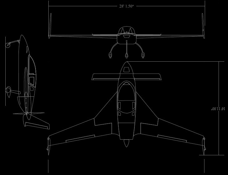
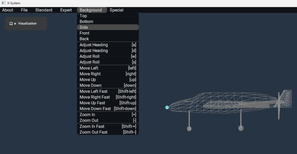
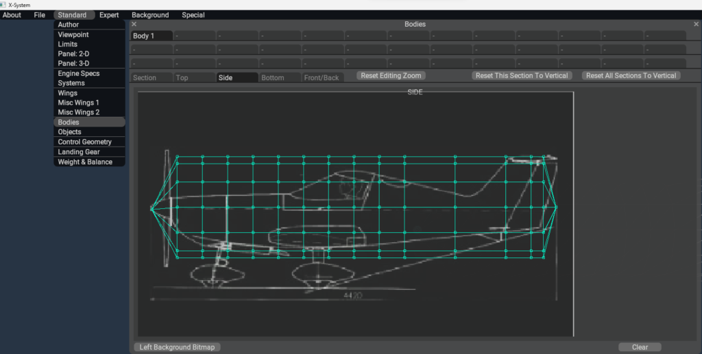
In the diagram you can clearly see the SIDE is selected in the BACKGROUND menu item. This automatically orientates the 3D model your working on to its beginning position. This is actually the CENTRE of your screen (the Picture is cropped).
The option here is when setting up your BODY which we will do soon you can either make the Lock point the NOSE by just adding rings behind it or you can split the building block rings by having say Five in front of the point and five behind the point allowing the central reference point to be always in the centre of the screen.
Save/Save As.
Let’s get started by first creating a folder in your X Plane 12 – Aircraft – “Your Aircraft Folder”. I’d recommend not putting it in the Laminar Folder. Creating a separate folder in the Aircraft main folder should work fine and keep your projects/creations separate and could save issues latter on. Inside this folder create a folder for your aircraft. Eg Cosy Mk IV.
Inside this place create a Research Folder for ease of management and place all your POH, Diagrams and specifications for your aircraft. K, now we can start. Open Plane Maker and I’d recommend having a shortcut to it on your start menu. To create a shortcut to your Plane Maker or any aircraft you build right click on the file and select shortcut. Its then possible to copy this to the desktop for quick access. It’s a personal choice whether you do this or not, but I have found it useful.
Plane Maker is located in your main X Plane 12 Installation folder. I’d you’re on XP 11 or any other version it’s the same. Let’s Build!
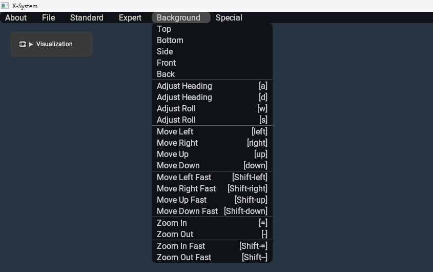
Essential Mouse Keyboard Controls for Success.
Controls you need to know are pretty easy so let’s get go over them. You should be familiar with these, and life will be easy.
- Mouse Left – Select
- ZOOM = + & – Background and model.
- Shift + & +/- is a fast zoom option. A / D (Shift +/ Shift – Fast Zoom)
- Rotate Model Horizontally – A / D (Shift +/ Shift – A / D = Fast Rotate)
- Rotate Model Vertically = W / S = (Shift + W / S = Fast Rotate)
The whole manipulation of foreground pictures and background pictures is super easy and getting your model over the required reference drawing and scaled correctly is easy.
Aircraft V Speeds Menu – Essential Starting Point.
When building your own aircraft in Plane Maker it needs to know parameters like speeds. These include stall, flap extension, gear extension, best climb, max speed in turbulence, maximum allowable speed and the never exceed speed. These are entered into one single easy menu. Let’s look at the menu and also what all the C speeds are in the graphic below.
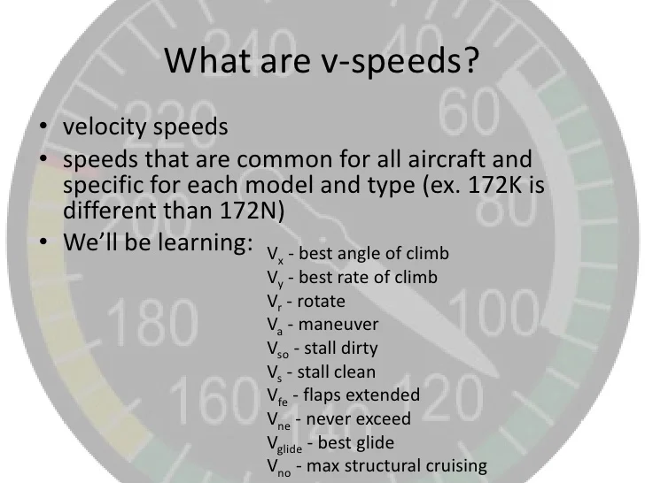
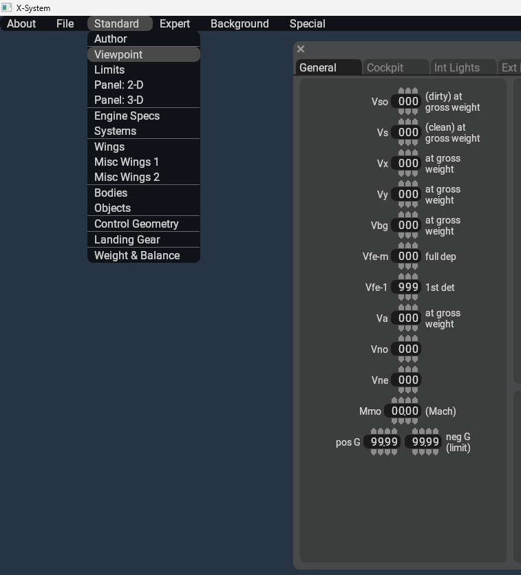
The most important are the stall speed (Vs) as well as your Maximum allowable airspeed (Vno) as well as Never exceed speed (Vne). Note the VNE is your flyable maximum airspeed in smooth air and the aircraft will break up at VNO. The additional airspeeds help X Plane understand your flying parameters along with weight & Balance plus aircraft design specifications like maximum positive and negative allowable Gs which is at the bottom of the list (Pos-Gs /Neg-Gs).
Engine Selection Parameters – Prop Selection.
Engine parameters are also an important part of ensuring your success when you build your own aircraft in Plane Builder. You can choose the type of engine from piston to turbine as well as Jets and even rockets if you wish. Maybe you could build the X-1 or other experimental aircraft. This is where your research will come to the fore again with maximum power figures for your engine type as well as maximum RPM which can be related to N1 for example in a jet engine.
Coupled with this is adding how many engines and locations of each. It’s possible to have as many as you desire pretty much in X Plane 12. Why not build the North American XB-70 Valkyrie with its six afterburning jet engines and see how fast you can fly.
Bodies – Views & Controls.
Getting started on shaping your aircraft starts with the BODIES menu where you can design your fuselage in a number of windows. Please also remember you can use these menus and reference the large master model at the same time if you wish. It’s easy to lose perspective so doing so can really prevent you from messing something up badly when your new!
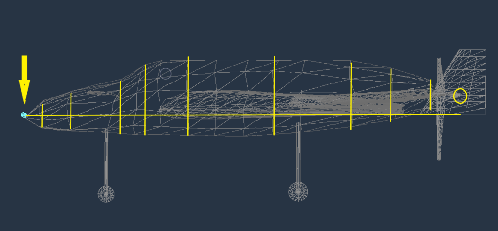
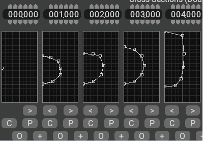
The main BODY view allows you to select the number of stations to shape your fuselage. There are basically two chains of thought setting this up. The reference point will remain constant, and everything will relate to this point. So, in selecting how many subsections you can manipulate as well as how far apart they are you can also select the reference point position. You may ask why is this important?
Well, if you always want the centre point of your aircraft in the centre of your screen then when you add building points Plus and minus the reference point so it will look like the diagram below. Personally, I prefer so far to keep the reference point at the front so I can easily understand how far each building ring is from the nose. I know the spinner needs to have two points close together and anytime there are big shape changes Its good to have them near this area spaced evenly apart.
Look at the diagram below to see examples of both ideas. Look at the BLUE Circle showing the reference point and the numbers in the top of the box showing the reference distance from the dot. The interface allows up to 20 individual sections with 5 to 7 sections in each. These you can shape your aircraft like taking a slice through the body at each point.
The individual dots can be used to shape each section allowing for canopies, air intakes as well as the general round or square shape of the fuselage. This view is a mirror so represents only half of the fuselage as you look at it. This ensures your work is mirrored perfectly on the opposite side.
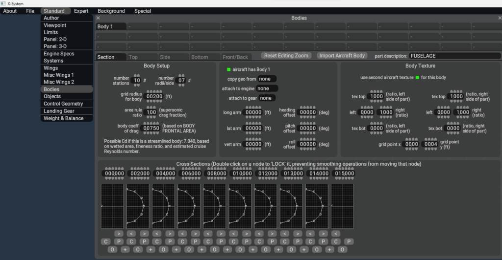
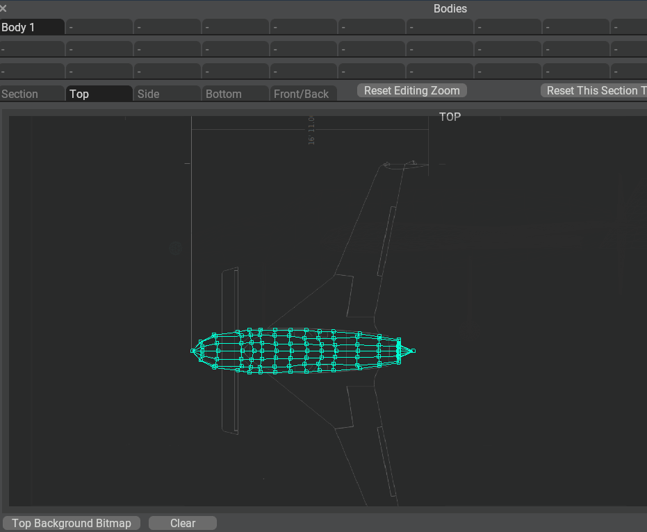
The additional views are Top – Side and – Front/Rear accessed by using the Central tabs above the Settings parameters box. Very useful in building specific aspects of the model and as always remember you can reposition the primary model and the window so as to have a reference on each.
The Controls in BODY.
The Controls immediate under the box are very useful ones.
- The top numbers are the distance from the Blue Reference point.
- Positive numbers add behind the point. 0150.00 = 15 ft behind the Ref Point.
- Negative Numbers place the frames in front of the reference point. -012.00 In front of the Ref Point.
- The ARROWS < > copy the current frame in the direction you click.
- The C copies a frame, and you can copy it into any other frame.
- The P copies a frame, and you can copy it into any other frame.
- The O rounds the shape automatically. Great for circular fuselages.
- Plus + adds a new frame between the current and next frame.
Note again the boxes are as if you’re facing and looking through the fuselage like an X Ray or MRI. You’re looking at one half that is mirrored on the other side.
Wing Building Concepts.
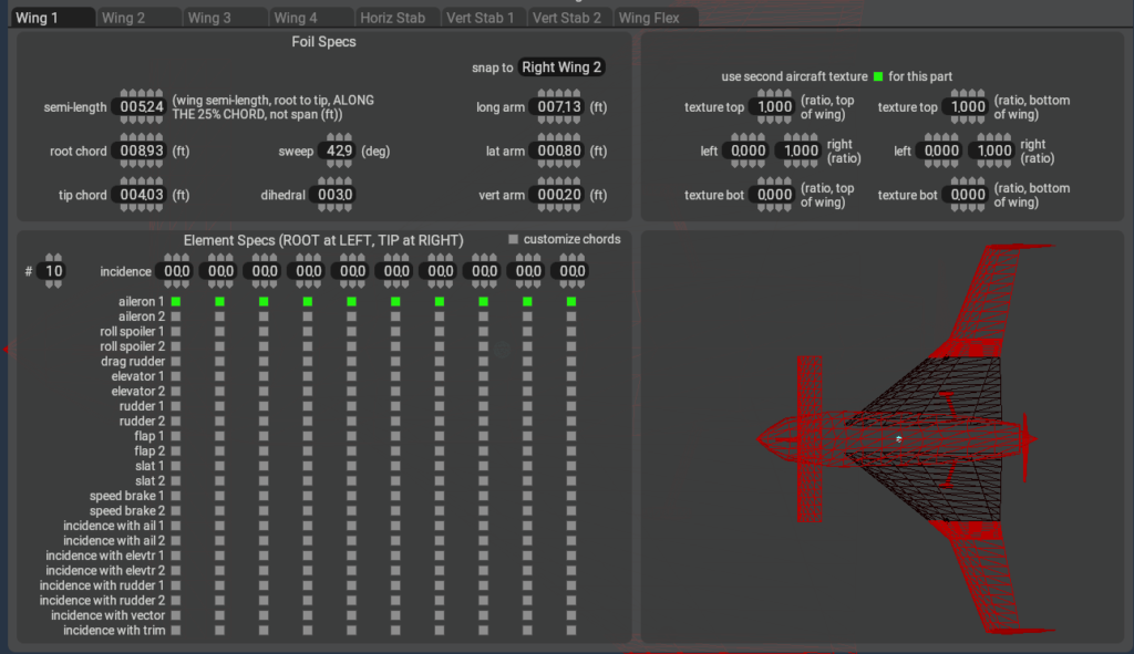
- Semi-Length = Total Wing Length of each section.
- Chord Root = Root (Base) Width.
- Tip Chord – Tip Width.
- Sweep = Sweep Angle.
- Dihedral = Dihedral Angle Up/Down.
- Snap to Sticks sections to specific wing.
- Long Arm – Distance from Reference Point.
- Lat Arm = Distance from the centre of the Fuselage.
- Vertical Arm = Vertical reference Plus /Minus from the reference point.
- ELEMENT SPECS / Make Control Surfaces – Select any control surface Types here. Aileron/Elevator/Rudder etc.
- Note full width tick all the green boxes. Central don’t click the right or left end boxes.
- Use Second Aircraft Texture = Disregard for Now.
In the example above I am building a Cosy Mk 4 using three wing sections to create the angles to follow the wing. It’s not possible to create curved sections as far as I know. The Rudders are created using the Vertical Stab and as in this case you can have two. The wingtips are created separately. The canard is created in the horizontal Stab tab and follows the same process.
Making the actual control surfaces such as aileron, elevator and rudders is in the next section as it uses separate input box called Controls in the same Standard menu tab.
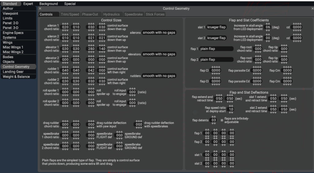
Add Control Surfaces Easily.
Control surfaces are super easy to create for your aircraft by simply adding in the size of the tip and roots of the surface then tell the program your deflection either up and down or sideways for the rudder. Adding additional figures you can add spoilers, slats and flaps as well with the same simple process.
- Latest CPU’s Available Now – Amazon.com
- Get a NEW GPU Best Performance – AMAZON.com
- Upgrade RAM Here today – AMAZON.com
- Prebuilt PC Options – AMAZON.com
Weight & Balance – Guide.
Weight and Balance are a crucial part of making your aircraft fly well. The tab requires you use diagrams of your aircraft and spec sheets to fill in passenger locations, weights, luggage weights, fuel tank locations, weights for all both full and empty to make an aircraft that is stable to fly. Honestly its not to hard so let’s dive in.
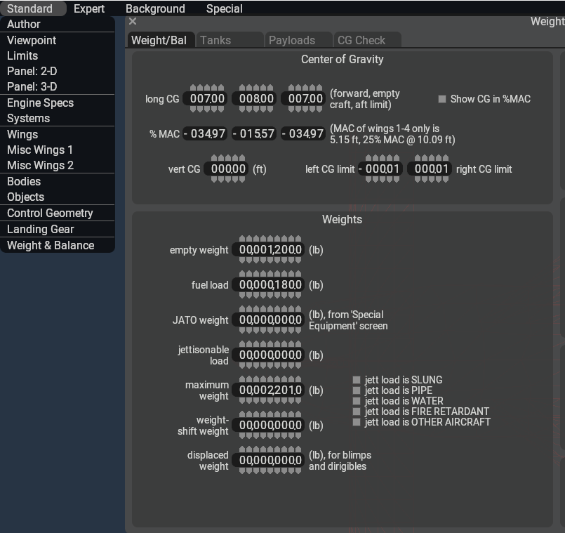
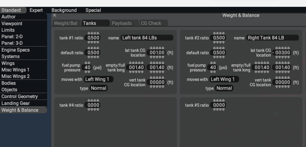
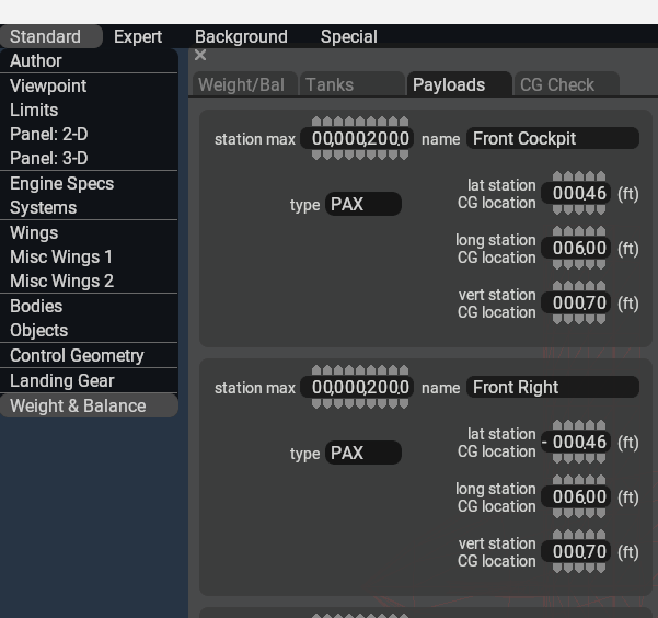
Selecting the Weight and Balance at the bottom of the Standard Menu gives you four tabs. Weight/Balance ie the aircraft weight and balance itself then the second and so forth. Checking your research for the location of the C of G is crucial. In my experience with my Cosy Mk IV so far this may not be exactly the correct place for your model. The C of G windows is still a mystery to me so let’s tune with X Plane 12 as the aircraft customise menu has C of G there and this is easier and visually more representative.
It shows the forward and rearward most points of the aircraft. Then its a matter of moving the aircraft C of G location and I moved all the fuel and passenger points over this one to start. Working with one central point is easier I have found.
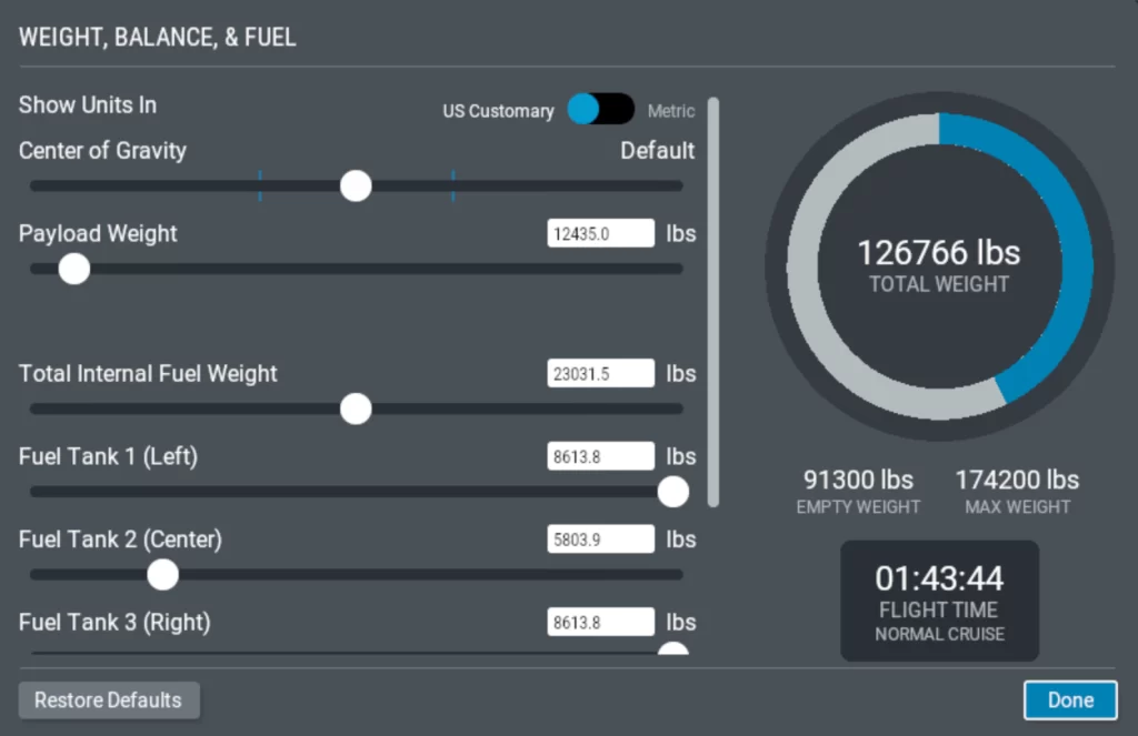
Test flying my Cosy Mk IV with a check of all the wing locations, correct lengths and wing areas it was apparent the C of G was to far forward and the aircraft would not take off. Moving the C of G back just a couple inches made a big difference, and I got my first test flight in with flight from Adelaide airports longest runway.
The flight test proved the C of G was still forward of where it needed to be as I could not slow down below 100 knots without losing control. Further testing will enable me to fine tune my Cosy further. It’s a time-consuming process editing in Plane maker then jumping to X Plane 12 to test then back again to edit issues found.
This is the C of G in X Plane 12, and it shows current C of G location in the middle which should be good for flying. Adjusting the total fuel as well as payload ie pilot, passenger and luggage weights which are all individually placed in Plane Maker.
I would certainly work on the overall C of G, so the aircraft flies as expected then move the locations of the pilot, passengers and fuel tanks one at a time to check the effect. Again, this is more time but worth it if you want a realistic loadout weight distribution.
Wing Airfoil Application – It’s Easy!
The airfoil tab will allow you to set up specific wing designs. These are numbered and are simply applied to each component individually. This will ensure your aircraft reacts as you expect when you’re flying it as well as giving X Plane the information on how the air should pass over and under each surface. For the best realism you want to try and find what type of AIRFOIL your aircraft has by design. Some research should allow you to find this out. Pilot Operating Manuals (POH) often have this information included in the specifications area.
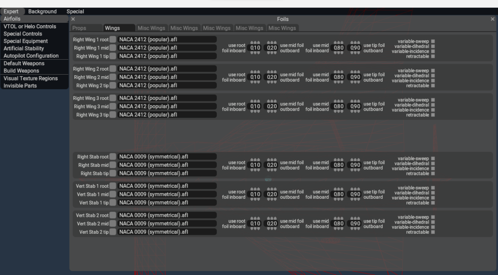
From the EXPERT tab you can enter the air foils for your aircraft. Doing the research, you may have to download the specifications from online. I have seen these available but at the time of writing I have not installed one of my own. Note if you need a specific air foil you can create it in the X Plane 12 Air foil Maker program included as with Plane Maker and World Editor.
Instrument Panel 2D /3D.
X Plane by default will give you an option to build a 2D cockpit but if you’re planning to fly in VR or with head tracking your also going to need a 3D cockpit. There are some interesting options here I have seen online. I saw there is an option to import both 2D/3D cockpits from another aircraft and use them.
In your build your own aircraft dream you will need at least a 2D cockpit option you can simply click and place instruments in the basic template and save it giving you a reasonably good 2D cockpit to go test fly your aircraft. Its just a Drag and drop process so not difficult to get started for sure. The 3 D cockpit is a different animal, and I would like to point you to WEH Videos YouTube channel. Skip, the owner made a great video and it’s very easy simple guide to making a 3D cockpit. Done from scratch if you watch this series you’ll be grinning in no time!


What you Can & Cannot Do with Plane Maker.
Plane Maker can be considered the skeleton of your project. With Plane Maker you give your dream aircraft the essential shape and parameters so it can fly in X Plane 12.
In the Tabs you can select each of the building screens as well as the aircraft speed limitations, weights, fuel, passenger and luggage parameters as well as engine, prop specifications.
It is also possible to create a 2D cockpit adding quality instruments, MFDs as well as a HUD should you need one.
On completing the aircraft in X-Plane 12 plane maker you will have a fully flying functional aircraft you can fly and enjoy.
Additional Programs.
What you won’t have is a high-quality exterior model, 3D Cockpit with high quality textures. To take your aircraft towards a professional level is some additional programs. A paint program like Gimp which is a freeware download. Build your 3D external body with BLENDER, a free 3D program and more like Audacity to create Sound Files for your aircraft.
Test Flight & Adjust.
Great to see you made it this far in our dream to build your own aircraft. I hope you have your aircraft ready to fly and it’s time to test it out. It’s likely you may find issues so have a pen and paper ready, so you don’t forget the issues. Starting X Plane, you will find your aircraft waiting for you without a picture but that doesn’t matter. Click on the Customize button and check your C of G is in the middle so at least the aircraft will fly for you.
If its ok hit start and go take a flight in your shiny new basic aircraft. We will paint the aircraft next but making sure its flying ok is an important start. Giving it a paint job now and then adjusting wings or other objects will require you doing your paint job again so be patient. This has proven to be a frustrating point for myself just getting it to fly as I expected so be prepared to do some more work if its not flying as expected.
Paint and Design.
When you build your own aircraft it will need a paint job. Painting the aircraft especially if it’s a scratch-built aircraft is fairly easy. You can simply output a file from the Points Menu, and it will create two files you can then paint and be applied to your aircraft. If you make a basic white first, then you have a basic point to copy and repaint to your hearts content latter.
Should you have just modified a previously created aircraft then you may already have a paint kit available and simply go to town repainting a new livery of your own in 3D paint, Gimp or other paint program.
AUTHOR.
Brendon McAliece is a multi-lingual expat who brings over three decades of flight simulator/PC building experience as well as over two decades of real-world jet fighter experience as a weapons/egress technician. He holds a sport pilot certificate giving him real-world flying experience.
His travels have taken him from Europe to the Middle East, Asia and his home of Australia. He has a passion for travel, languages, Flight simulation as well as Guitaring and Coffee. You can read more in his blogs below.
Learn More @ DreamingGuitar.com – DreamingCoffee.com – LetsFlyVFR.com
( HOME – BLOG – SHOP – ABOUT )
As an Amazon affiliate I may benefit from qualifying sales.